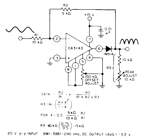
Full Wave Rectifier Circuit Diagram
Rectifier tapped circuitglobe diode 12+ draw the circuit diagram of full wave rectifier Build a full wave rectifier circuit diagram
Half Wave & Full Wave Rectifier: Working Principle, Circuit Diagram
Full wave rectifier – circuit diagram and working principle » electroduino Full wave rectifier tutorial and circuits What is full wave rectifier ?
Full wave rectifier circuit working and theory
Rectifier wave circuit filter without bridge diagram tapped capacitor diodes center four type circuits board using circuitdigest electronic choose twoRectifier principle Full-wave rectifierRectifier waveform tapped dc load voltage capacitor resistor.
Wave rectifier diode voltage waveform circuit tutorial circuitsFull wave rectifier circuit diagram in multisim Rectifier tapped principleRectifier wave circuit diagram working types theory.

Rectifier circuit output principle
Half & full wave rectifier[diagram] 24v rectifier wiring diagram What is half wave and full wave rectifier?Wave rectifier half circuit diagram working alternation positive current figure.
Precision full wave rectifier circuit diagramRectifier circuit diagram Precision rectifier circuit using opamp working and applicationsRectifier study.

Full wave bridge rectifier circuit [multisim simulation]
Rectifier cbse diodesRectifier wave circuit output waveform input etechnog wiring Rectifier wave circuit output input educateRectifier wave circuit working bridge voltage tapped output centre transformer across load advantages consists.
Full wave rectifierRectifier wave circuit half bridge ac dc basics Rectifier multisim diode waveform tapped operation voltage circuitstoday circuitsRectifier precision circuit opamp tutorial electronics.

What is single phase full wave controlled rectifier? working, circuit
Wave rectifier circuit principleDictionary of electronic and engineering terms, full-wave rectifier circuit Full wave rectifier : circuit diagram, types, working & its applicationsFull wave rectifier bridge rectifier circuit diagram with design theory.
Rectifier wave bridge circuit multisim diagram simulation diodesRectifier wave center tap working circuit diagram disadvantages advantages Rectifier circuit diagram without transformerSchematic structure of the full-wave rectifier under study..

Rectifier wave circuit precision diagram simple ac dc circuitsstream circuits sourced gr next
In-depth guide to full wave rectifierHalf and full wave rectifier working principle Half wave & full wave rectifier: working principle, circuit diagramRectifier circuit wave diode terms diagram dictionary electronic engineering.
Full wave rectifier – circuit diagram and working principle » electroduinoRectifier circuit capacitor smooth waveform circuitglobe resistor filter advantages robhosking Full wave rectification diagramFull wave rectifier: working principle, diagram, and formula.

Rectifier transformer tapped waveform
Half wave & full wave rectifierRectifier circuit diagram Half wave & full wave rectifier: working principle, circuit diagramRectifier wave half circuit diagram rectification diode ac operation crystal connected used supply shown below through.
12+ full wave rectifier circuit diagramDraw the circuit of a full wave rectifier using two p-n junction diodes Rectifier wave circuit theory capacitor working load rl do calculate diagram bridge half output dc types itsFull wave rectifier circuit diagram (center tapped & bridge rectifier).


Half Wave & Full Wave Rectifier: Working Principle, Circuit Diagram

In-Depth Guide to Full Wave Rectifier - Circuit Diagram, Waveform

Half & Full Wave Rectifier | Converting AC to DC | Rectifier Basics

Rectifier Circuit Diagram | Half Wave, Full Wave, Bridge - ETechnoG

Half and Full Wave Rectifier Working Principle | Circuit Diagram

Half Wave & Full Wave Rectifier | Working Principle | Circuit Diagram