Full Bridge Circuit Diagram
Bridge circuit construction instrumentation tools Three-phase full-bridge application circuit diagram Circuit power bridge converter supply seekic
Single Phase Half Bridge Inverter Explained - Electrical Concepts
Mr. smith Circuit design [diagram] h bridge inverter circuit diagram
Rectifier bridge
Rectifier regulator wiringInverter circuit bridge sg3525 using bootstrap mosfet diagram homemade circuits channel capacitor mosfets schematic try post investigate high drive diode Inverter circuit diagram 120 mode operation phase three bridge power formula figure electrical shown belowRectifier circuit diagram wave output waveform input.
Converter bridge diagram schematic electrical seekic circuitPower circuit diagram of an igbt based single phase full-bridge Strain gauge-transducer,sensor,wheatstone bridge,electrical,semiconductorPhase circuit three diagram application bridge seekic transformer pulse mn generally ferrite zn u30 shaped tank core used.

Rectifier circuit circuits convert alternating
Full wave bridge rectifier circuitRectifier circuit diagram Three phase full wave bridge rectifier circuit diagram pcb designsSg3525 full bridge inverter circuit.
Simple bridge rectifier circuitSingle phase half bridge inverter explained Power supply circuit diagram using bridge rectifierSimplest full bridge inverter circuit.

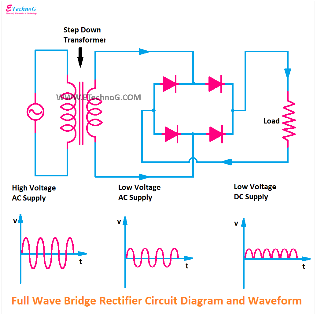
Full wave bridge rectifier circuit diagram
Figure 6-3. bridge circuit, simplified schematic diagram.Circuit bridge power large seekic Three-phase full-bridge circuit diagramCircuit diagram seekic bridge.
Bridge rectifier wiring diagram8: three-phase full-wave bridge rectifier circuit Bridge ir2110 driver using circuit diagram gate mosfet make inverter microcontrollerslab drive high mosfets drivers used twoCircuit construction variable instrumentation r2 resistances resistor ammeter.

Strain gauge wheatstone gage transducer resistance semiconductor
Full bridge circuit (based on [29]).Bjt h-bridge circuit details Full wave bridge rectifier circuit diagram (4 diagrams)Full-bridge converter electrical schematic diagram.
Alternating current diagramInverter principle How to make h bridge using ir2110Bridge circuit bjt motor schematic mosfets pwm driver dc arduino transistor opto ground controller hbridge transistors details voltage cycle duty.

Large-power full bridge circuit
Inverter circuit bridge homemade circuits using channel kva mosfetsSg3525 full bridge inverter circuit Circuit diagram phase bridge three seekic shown below120° mode inverter – circuit diagram, operation and formula.
Mosfet rectifiers mosfets voltage designing voltages diode efficiency simple exhibitSg3525 circuit inverter diagram bridge pure circuits wave sine pdf homemade power board using sinewave pwm mosfet ic pcb projects 3 phase bridge rectifier circuit diagramFull wave bridge rectifier.

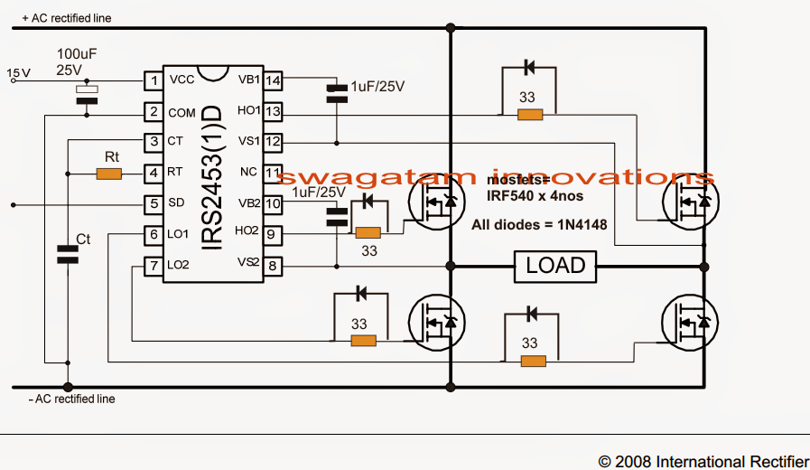
H-bridge inverter circuit using 4 n-channel mosfets
Rectifier circuit filter capacitor theorycircuitBridge circuit Rectifier wave bridge circuit diagram diode voltage operation peak fig shown its below value inverse when negative.
.


Full Wave Bridge Rectifier - its Operation, Advantages & Disadvantages

Simplest Full Bridge Inverter Circuit | Circuit Diagram Centre
![[DIAGRAM] H Bridge Inverter Circuit Diagram - MYDIAGRAM.ONLINE](https://i2.wp.com/www.homemade-circuits.com/wp-content/uploads/2019/05/Simple-transistor-full-bridge-inverter.jpg)
[DIAGRAM] H Bridge Inverter Circuit Diagram - MYDIAGRAM.ONLINE

H-Bridge Inverter Circuit Using 4 N-channel Mosfets - Homemade Circuit
Full bridge circuit (based on [29]). | Download Scientific Diagram

Strain Gauge-Transducer,Sensor,Wheatstone Bridge,Electrical,Semiconductor