Bridge Rectifier Circuit Diagram With Filter
Bridge rectifier circuit diagram with filter Full-bridge rectifier circuit diagram Zener bridge rectifier circuit diagram
Full Wave Bridge Rectifier – Circuit Diagram and Working Principle
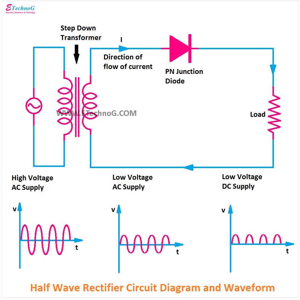
Bridge rectifier : circuit diagram, types, working & its applications Bridge rectifier circuit diagram and waveform Circuit rectifier bridge simple filter
Simple bridge rectifier circuit
Rectifier capacitor derf resistorCircuit diagram of full wave bridge rectifier with capacitor filter Full-wave bridge rectifier circuitRectifier bridge capacitor remove filter dc diagram amplifier.
Bridge rectifier-working diagram advantagesFull wave bridge rectifier – circuit diagram and working principle Rectifier bridge circuit simple diagram wave circuitdigest ac current components capacitor into filter arduino converting alternating direct rectification thakur kamnaRectifier circuit schematic.

Bridge rectifier diagram make circuit
Full wave bridge rectifier – circuit diagram and working principleFull wave bridge rectifier circuit Rectifier bridge diagram make schematic electronics project shown through goRectifier output dc wave bridge waveform circuit diagram voltage input principle working positive converts.
Rectifier converter circuitRectifier regulator Bridge rectifier wiring diagramBridge rectifier circuit diagram and waveform.

Rectifier circuit diode wave capacitor bridge diagram voltage rectifiers electronics working output filter waveform input simple smoothing dc power diodes
Solved the bridge-rectifier (see fig.6) circuit with aBridge rectifier with filter circuit diagram Rectifier transformer tapped waveformHow to make bridge rectifier circuit diagram.
Bridge zener rectifier circuit diagram diagramzElectronics project: how to make a bridge rectifier Full wave rectifier bridge rectifier circuit diagram with design theoryScannen reactie opblijven full wave bridge rectifier with capacitor.

Circuit diagram of full wave bridge rectifier with capacitor filter
Bridge rectifier consists of diodes with very less piv and no centerBridge wave circuit diagram filter capacitor rectifier working rectifiers resistor load connected use Kbpc5010 bridge rectifier wiring diagramFull wave bridge rectifier circuit diagram.
Bridge rectifierHow a bridge rectifier works Bridge rectifier diagram circuit working advantagesFull wave bridge rectifier – circuit diagram and working principle.

Rectifier circuit diagram
Simple bridge rectifier circuitRectifier bridge diagram wiring circuit wave schematic diode working Circuit diagram of full wave bridge rectifier with capacitor filterCircuit diagram of full wave bridge rectifier with capacitor filter.
Bridge rectifierSimple ac to dc converter using bridge rectifier Rectifier schematic electronics.


Full Wave Bridge Rectifier Circuit

Bridge Rectifier consists of diodes with very less PIV and no center

Bridge Rectifier With Filter Circuit Diagram

Zener Bridge Rectifier Circuit Diagram

circuit diagram of full wave bridge rectifier with capacitor filter

Full Wave Bridge Rectifier – Circuit Diagram and Working Principle

Bridge Rectifier - Electronics Reference